Frame Resonance & Vibration Analysis: Carbon Fiber Mechanics & Gyro Contamination
A deep physical study on carbon fiber structural resonance, analyzing vibration transfer paths, frame stiffness parameters, and gyro noise prevention.
1. Structural Resonance of Carbon Fiber
Multirotor frames are cut from carbon fiber sheets. While extremely strong, carbon fiber possesses natural resonance frequencies ($150-300\text{ Hz}$). When the motors spin, they generate vibrations that match these frequencies, causing the frame to resonate.
2. Gyro Contamination Path
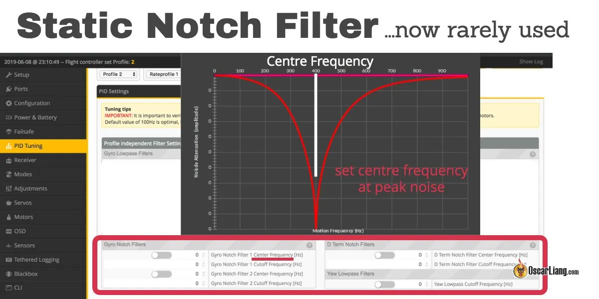
Frame vibrations are conducted directly to the Flight Controller (FC) board. The onboard gyro sensor registers this high-frequency noise, which corrupts the PID control loop.
[Vibration Contamination Path]
Motors ---> Arms ---> Frame Plates ---> FC Standoffs ---> Gyro Sensor
                         |                                  |
                   (Resonance Peak)                 (PID Loop Corruption)
2.1 Mitigation via Soft-Mounting
Soft-mounting the FC using silicone gummies isolates the board, acting as a low-pass filter to damp vibrations above $100\text{ Hz}$.
3. Frame Layout Stiffness Comparisons
- True X Layout: Symmetrical arms, balanced inertia, but narrow carbon plates can resonate easily on Pitch.
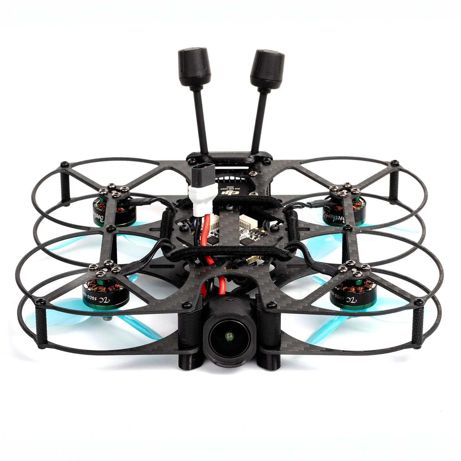
- Deadcat Layout: Front arms pushed out for clean camera views. The asymmetric geometry creates complex arm resonance frequencies, requiring separate filtering for Roll and Pitch.
RELATED GUIDES
Copyright-safe media generated locally by FPVLovers